Home Video Cameras & How to Connect Them
From the earliest days of portable video recording (circa 1970)
until the advent of consumer camcorders in the mid-1980's,
a variety of video camera models were produced for use with separate
videotape recorder decks. The de facto standard for connecting the two
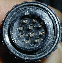
was a 10 pin circular connector with a threaded lock ring. First used
by Sony on early black & white cameras, the 10-pin connector was adopted by
nearly all other manufacturers. The basic pin-out became standard as well,
so that for the most part cameras and VTRs from differing brands would
work together. The cable with male connector is usually a permanent part of
the camera and plugs into a female chassis mounted jack on the VTR.
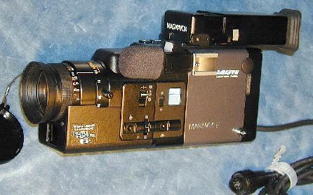
Today, few would consider a separate camera & shoulder-pack recorder a good
choice for portable video making, and indeed not many of the recorders survive in
good working condition due to the deterioration of their mechanical parts.
But the cameras are often in near-new condition and are available at reasonable cost.
They can be excellent for survelliance, Amateur TV, webcams, school studios, & the like.
This page is presented to help users get these fine older cameras working.
The typical "10-pin" camera requires 12 volt DC power for operation.
Depending on age & features, the current required can be in the range of 0.5 to 2.0 amps.
There are three basic ways to power up a camera:
1 -
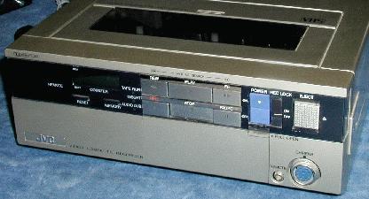
If you have an older video recorder with a mating 10-pin jack,
plug the camera into it. Record directly, or feed video & audio
elsewhere via the VCR's output connections.
2 -
Camera power supplies were offered by all the major manufacturers.
If you can find one, it also has the mating jack and audio/video outputs.
3 -
Make your own camera cable with a mating connector and a few parts.
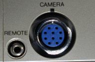
Making a cable is easy. The hardest part to obtain is the female connector to
mate with the camera; you won't find one at Radio Shack.
The connector is a Hirose Electric type RM15 model D.
The mating jack is RM15TJD-10S (inline) or RM15TRD-10S (panel mount).
The inline jack is currently available (2008) from Digi-Key for about $14.
Look for their part number HR1743-ND.
For the A/V outputs, cut one end off a stereo or A/V patch cable.
Power the camera with a 12v wall wart type AC adapter - this is an RS item, or
steal one off that old answering machine. Just make sure that the current
rating is adequate for the camera you're using (read the nameplates).
If you prefer to operate away from AC power, connect a 12v battery or a
automotive cigar lighter plug instead. Use a 2 amp fuse in the positive lead.
In any case, make sure the polarity is correct!
Here is the connection diagram:
Notes:
1 - Pins 3, 4, & 5 were used for various functions specific to the manufacturer
like status indicators, serial data to control functions on the tape deck, etc.
They are not required for the basic functions of the camera.
2 - The pause line is controlled by the camera record/standby trigger.
The polarity of this signal was not standard. Many cameras have a switch
to select the polarity to make them compatible with more VCRs.
It's not required for the basic functions of the camera.
After essentially setting the standard, Sony discarded it
in favor of a 14-pin connector that allows more features on the camera.
All the advice above applies to Sony cameras, but I don't have a source
for the required mating connector.
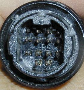
Here is the pinout for the 14 pin Sony "K" connector:
1 Camera video out
2 Video out shield
3 Camera video in
4 Video in shield
5 Camera pause.
6 Tally light
7 Camera audio out CH-2
8 Record review. (some VCRs)
9 Camera audio out CH-1
10 Audio shield
11 Camera audio in CH-1
12 Camera audio in CH-2
13 Power 12v (+) Input
14 Power ground